- Can 2 MRCC's be Connected Together?
Yes, you can connect 2 MRCC’s together and remotely route outputs!
This feature was added after MRCC started shipping, so it might require a firmware update. Get it from the Download section, or check the forums MRCC Open Beta Firmware section for pre-release firmware and release notes. You must be logged into the forums to see this.
When 2 MRCC’s are connected, the Y guy lights up in the top right corner of the screens of both MRCCs.
Route MIDI Outputs on the 2nd MRCC by holding the Remote routing button. It is left of the encoder, and marked with the Y guy. Press and hold the Remote routing button on each MRCC to see what remote outputs are routed from the selected Input port.
Save your settings on each MRCC to save the remote routings you created.
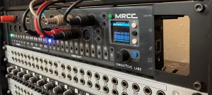
MRCC’s are connected using a CAT6a shielded Ethernet cable plugged into the RJ45 on the right side of the MRCC. The best kind of Ethernet cable has metal shrouded connectors that are connected to a drain wire in the cable. We have tested up to 32 feet (10 meters) with a CAT6a cable. You might be able to go longer, maybe up to 50′ with a good cable. A regular Ethernet cable might also work for shorter distances, like 6 to 10 feet. YMMV
The MRCC to MRCC electrical connection is not MIDI, but a high speed serial interface. The MRCC to MRCC cable does not factor into the MIDI spec cable length limit of 50 feet. Therefore, you can still use long MIDI cables on each MRCC.
- Can MRCC be Rack Mounted? How are They Installed?
Yes, Rack Ears are available as an accessory. The MRCC is a 2U device and can be mounted in a standard 19″ rack with the optional 2U Rack Ears.
The rack ears replace the existing desktop side panels. You will need a 2.5MM hex head driver to remove the screws.
Remove the 4 screws from each desktop side panel and remove the panel.
Hold the right side rack ear, the large one with a big hole, so the connectors on the MRCC align with the holes in the rack ear. Then start threading the 4 screws by hand before tightening. The screws should be snug but be careful not to over-tighten them as not to strip the holes in the enclosure.
Install the left side rack ear, then mount it in your rack!
- Can MRCC be Updated?
Yes! Conductive Labs will provide periodic firmware updates to add features or fix issues reported in our MRCC User Forums.
- Does MRCC Route MIDI SysEx Messages?
Yes, but there were some limitations prior to firmware version 1.0.051 (March 2022). Check for the latest firmware updates on the MRCC download page, or for pre-release versions on the MRCC Open Beta Firmware forum.
Before version 1.0.051:
MRCC could route SysEx (MIDI System Exclusive messages) from any MRCC input to outputs 1 through 6 (5 pin DINs). Outputs 7 through 12 did not support SysEx.
The Remote 7 would only route SysEx when configured as MIDI thru for outputs 1 thru 5.
As of firmware version 1.0.051 (March 2022), SysEx is passed on all MRCC DIN and TRS outputs, and Remote 7 outputs. Passing SysEx between two MRCCs connected with an Ethernet cable is not currently enabled.
Most vendors recommend connecting their MIDI devices directly to the computer for firmware updates.
- How Does the MRCC Remote 7 Work?
The Remote 7 accessory for MRCC extends MIDI ports to where you need them in your studio, up to 50′ away, and adds 5 additional MIDI outputs!
The Remote 7 is connected to MRCC via an Ethernet cable. The cable is connected to MIDI outputs in the MRCC and those ports are connected to the Remote 7. The RJ45 ports are not Ethernet ports, do not connect Ethernet devices, it may damage the MRCC or your Ethernet device.
When the Remote 7 is connected to MRCC, the MRCC will detect and enable it after a power cycle.
The 3.5MM TRS ports are attached to Remote 7 ports 1 and 2. The 3.5MM port attached to Port 1 is an A type TRS MIDI (the format adopted in the MIDI specification, and used by Korg and others), and the 3.5MM port attached to Port 2 is a B type (as previously used by Arturia and others). Its safe to try both ports to see which works with your MIDI equipment. And both the 5 pin DIN and 3.5MM output attached to it can be used at the same time.
Upon initial release of the MRCC, the Remote 7 ports acted as “MIDI thru” for MRCC outputs 1 thru 5. As of firmware version 1.1.020, the Remote 7 can be configured as five additional individually routable ports configurable on Settings page 2. In the “Remote 1-5” mode, use the Remote button (marked with the Y guy to the left of the MRCC’s encoder). While holding that button down, select the output 1 thru 5 to route them. The LED for that outputs turns yellow. Hold the Remote button to see what Remote 7 outputs are routed.
- What Causes the MRCC USB Hub Port to Have an Amber Color LED Indicator?
The MRCC USB Host Ports are USB 2.0 specification compliant. These ports have over-current sensing protection circuits, which when tripped will remove power from the USB device that is connected to MRCC. When this happens the LED indicator next to that USB port turns an amber color (instead of green). This protects MRCC from being damaged by faulty USB devices.
Over-current protect can happen with USB devices that require an external power supply but do not have the power connected, or it is drawing more current on power-up than what the USB 2.0 specification allows.
If your device is triggering USB Host Port over-current protection:
- First turn off MRCC with the power switch. This resets the power protection circuit.
- Try using the external power source with your device, and turn it on before switching on MRCC.
- Switch on MRCC. A good USB connection will be indicated by a Green LED indicator next to the MRCC USB Host Port.
- What Devices Work in the MRCC USB Host Ports?
The MRCC’s four USB 2.0 host ports are designed to support USB MIDI Class Compliant Devices. That is, USB MIDI devices that do not require a special driver to function. The USB host ports are designed to work best with USB MIDI controllers.
The host ports can also accommodate a standard USB keyboard for entering port labels.
At this time, the USB Host ports do not support a USB hub for expanding the number of ports. We plan to investigate adding hub support. Keep an eye on the MRCC user forum for announcements of firmware updates.
Check out the MRCC USB Host Port Compatibility Tracker for reported compatibility with specific devices.
One way to tell if the device is USB MIDI Class compliant or not; if you have to install a driver on Windows or Apple OS to use the device, then it’s probably not class compliant. However, there are exceptions. For instance, some Korg devices, like the nanoKontrol will use a driver that is required to configure the device, but also works fine as a USB MIDI device without the driver. Many Roland devices come configured to require a driver, but can be re-configured to be USB class compliant instead.
If you are having trouble with a device, please check with the vendor of the device to find out if it is supposed to be USB MIDI Class Compliant.
USB is a complex and timing sensitive interface. Some USB MIDI devices may pose problems for the MRCC USB host ports. Please report your experiences on the MRCC user forum. We will do our best to address compatibility issues, but cannot guarantee success with every device. Using the 5 pin DIN is always a good option if your device has it. Performance is the same whether using 5 pin DIN or USB on MRCC.
- When Will MRCC Ship?
MRCC and MRCC accessories are shipping now.
- Why are there errors sending SysEx messages over USB?
When sending “large” MIDI SysEx (System Exclusive) messages over USB to 5 pin DIN ports, some throttling by the sending software is required. Otherwise, USB data rates will quickly overflow the MRCC’s buffers since the data is coming into the MRCC much faster than it can be sent on 5 pin DIN ports. Over 5K bytes would be considered “large”.
To ensure reliable SysEx transfers, make sure the software sending SysEx messages has some delay between buffers. Also make sure buffer sizes are set to what is specified by the gear maker that is receiving the SysEx messages.
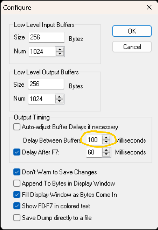
For example, using the venerable MIDI OX, open the SysEx configure window:
Click View -> SysEx…In the SysEx window, click SysEx -> Configure…Uncheck “Auto-adjust Buffer Delays if necessary”.Set “Delay Between Buffers:” to 100 Milliseconds. The “Delay After F7:” parameter should not affect the transfer, but it may be required by the receiving MIDI hardware. Follow the instructions provided by the maker of your MIDI gear.
 - Will a MIDI Controller Configuration Program Work With a Controller on MRCC's USB Host?
It depends on the method used by the configuration program to detect and connect to the MIDI device. The USB Host Ports on MRCC are not a USB hub connected to your computer. When using the USB Host Ports, the MRCC is hosting the USB devices, so your computer will not see it. Your computer will only see the 12 MIDI ports on the MRCC’s PC port connection.
A configuration program that looks for the USB MIDI controller in the computer’s enumerated USB device list will not see the device if the device is not connected to the computer’s USB port.
Some programs have you select a MIDI port and channel to find the device, and these might work with the MRCC’s USB Host since its just a matter of routing the MIDI messages between the device and the PC.
If the MIDI device’s configuration program requires the device to be connected directly to the computer, you could possibly connect the controller to your PC with its USB connection, and connect the device to MRCC with a 5 pin DIN or 3.5MM TRS MIDI connection.
Please check with the vendor of the MIDI device for its requirements. It would be very helpful to report your findings on the MRCC support forum so we can update our compatibility list for the benefit of our user community.
- Will a MIDI device with a USB-C port work with MRCC's USB Host Ports?
Maybe… MRCC’s USB host ports are USB 2.0 standard “high speed” ports, supporting 5V, 500mA power. USB C is a super set of prior USB versions which could require more power than USB 2.0 ports offer.
A USB C data connection can be USB 2.0 or USB 3.0, 3.1 or 3.2, etc. The data connection is typically backwards compatible with earlier USB data standards. However, a USB C device may require a USB-PD (Power Delivery) power supply. Which means the device power is negotiated with the USB-PD power supply. MRCC USB 2.0 host ports will not work with a device that requires a USP-PD power supply, or has a power requirement higher than USB 2.0 5V, 500mA.
If the device is USB MIDI class compliant, and it has a USB C connector but only requires USB 2.0 specification power, then it should work.
Check with the vendor of your MIDI device if you are not sure. Check out the MRCC USB Host Port Compatibility Tracker for reported compatibility with specific devices.
- Will MRCC Route a MIDI Clock?
Yes, MRCC automatically routes MIDI clock from any input to any routed output, or multiple outputs.
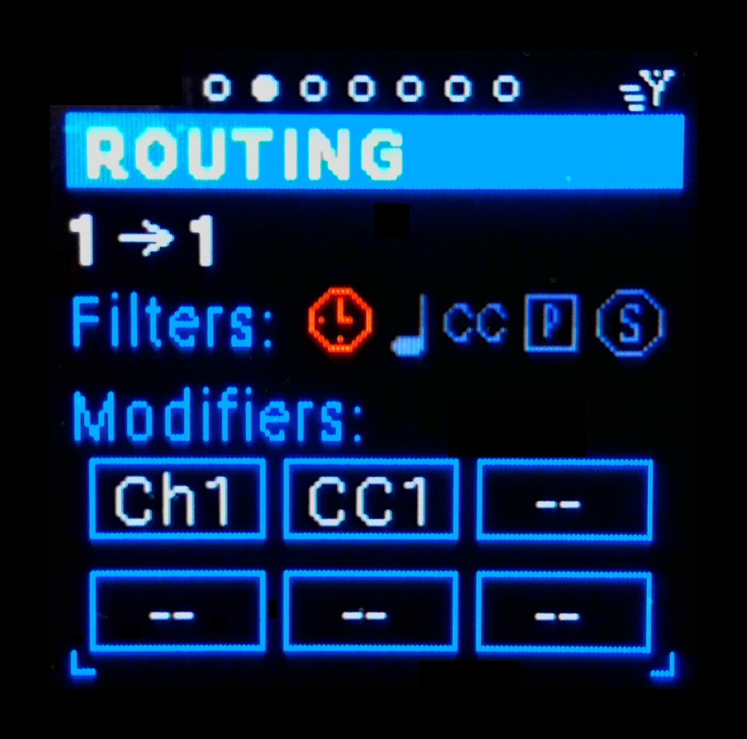
When you don’t want the MIDI clock to route, such as when there is more than one clock, its easy to set up a clock filter. Just toggle the Clock filter (red clock icon below):

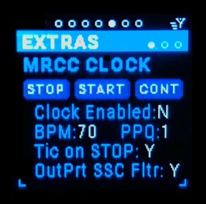
When using the MRCC MIDI clock, you choose which outputs to send the clock to while on the Extras -> MRCC Clock menu page. Press the output button for each output to send clock to, the LED will light red. When the MRCC clock is running, the input LEDs will blink in time with the BPM while on the Clock menu page.
The MRCC MIDI Clock can also be sent to a CV clock output (3.5MM jack). This is useful for syncing MIDI devices with modular or semi-modular synths. The CV clock out supports 5V and 12V outputs. It can be configured for 1, 2, 4 and 24 PPQ. Currently, the MRCC cannot send an external clock source to the CV clock out, but we plan to explore that for a future update.
MRCC FAQs